

SMART DISTANCE METER.

CHAPTER ONE
1.0
INTRODUCTION
Measuring
a distance by using a smart meter is greet for use now day. In construction and
for domestic usage, the measurement is from tape meter and other distance
measure equipment. Distance Measurement using microcontroller and Ultrasonic
Sensor. The ultrasonic sensor is consisting of Transmitter and Receiver
modules. Transmitter part ejects the pulse out and the receiver part receives
the pulse. If an obstacle is placed before the sensor, the transmitted
pulse ejected strike the obstacle and reflected back. The reflected pulse
is received by the receiver part. The time between transmission and reception
is calculated. This data is processed to calculate distance
1.1
Background
This
project implemented the ultrasonic sensor. Ultrasonic technology is one of the
solutions used to optimized balance between cost and the device features. The
ultrasonic distance measurer is used 'mainly when a non-contact measurer is
required. The Smart Distance Measurement Detector using ATMEGA 328P is an
efficient way to measure distance and check measurement value that is stored in
memory, where the device can record and recall distance measurements, 'allowing
several readings to be taken before copying them into paper.
1.2
PROBLEM STATEMENT
In
the construction field, the usage of electronic measuring device is still not
widely used yet. Due to the high cost of these equipment’s at market, an
economic way needs to think of in order to create an accurate measuring device
with low cost. Nowadays, measuring distance is considered as problem in
construction field or indoor measuring activities because this task is made by
using measuring tape. The problem will occur when using measuring tape where we
need at least 2 persons to measure between two distances. Besides, it is not
having a perfect accuracy due to parallax and obstacle in their way.
Therefore,
this project is necessary to do the process of measurement quickly and accurate
without doing measurement manually, it also has the advantages to store
measurement as many as 32 memories at one time.
1.2.1 Main
objective
The
main objective of this project is to minimize/reduce/eliminate parallax error,
calibration error and using long time to get reading.
1.2.2 Specific
objective
To
design an electronics smart distance meter that allows multi activities to take
place in many fields.
To
design an electronics smart distance meter that can save data in MEMORY CARD by
reducing data loss.
1.3
Methodology
On
performing my project, the following methods are used in order to achieve the
objectives of the project.
1.3.1 Literature
review
Under literature review, the reading different
books, consulting lecturers, notes from the class, visiting websites, explain
the features, operations and limitation of both existing system and proposed
system.
1.3.2 Data
collection
The
data were collected from different sources such as web site, domestic keepers,
magazines and radio.
1.3.3 Data
analysis
The
analysis has been done according to the operation of circuit by using different
formulas.
The
circuit has been designed to measure distance.
1.3.5 Simulation
Proteus professional software can have been
used to simulate the circuit in order to determine whether the circuit works or
not.
1.3.6 Building
prototype
The
circuit has been built on PCB board by using physical connection of components
It
was done by comparing the results from simulation and those that has been
observed after building the circuit.
1.3.8
Report writing
This involves preparation of the report book to include all activities conducted in first semester and second semester such as literature review, data collection, data analysis, designing, simulation, building, testing and report writing.
CHAPTER TWO
2.0 LITERATURE
REVIEW
2.1 The existing system:
This project is to design and create a better distance better distance measurement that can encounter the measuring problem. An ultrasonic measuring device is proposed to solve the problem as the ultrasonic using an ultrasonic sound. The ultrasonic transducer is operating at frequencies in between 40 kHz to 250 kHz. The concept for the project is using the LCD screen and displayed the reading of distance measured2.1.1 Disadvantages of existing
system
Reading obtained from the field can’t be used for feature
because haven’t stored.
2.2 Proposed system
for
the project is using the LCD screen and displayed the reading of
distance measured and user can save measurement to memory card for future uses.
2.2.1 Advantages of proposed system
- Save time to take measurement.
- Reduce/ eliminate/minimize the parallax and obstacle in their way.
- Allow multi activities to take place in distance measurement.
2.3 BLOCK DIAGRAM OF THE
PROPOSED SYSTEM
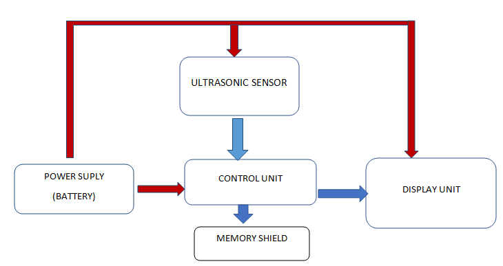
Figure 2: The block diagram of the proposed system
2.4
ULTRASONIC SENSOR
Ultrasonic
(US) sensors are also widely used to measure distances. Thus, they have
provided a reliable source of obstacle detections. Since they are not vision
based, they are useful under conditions of poor lighting and transparent
objects. However, ultrasonic sensors have limitations due to their wide
beam-width, sensitivity to specular surfaces, and the inability to discern
objects within 0.5 m. Because of the typical specular nature of the ultrasonic wave’s
reflection, only reflecting objects that are almost normal to the sensor
acoustic axis may be accurately detected. Most ultrasonic sensors use a single
transducer to both transmit the sound pulse and receive the reflected echo,
typically operating at frequencies between 40 kHz and 250 kHz. A variety of
different types of transducers are used in these systems. Ultrasonic is one of
the distances measuring sensors that had been studied.
Ultrasonic transducers measure the amount of
time taken for a pulse of sound to travel to a particular surface and return as
the reflected echo Typically, an b ultrasonic rangefinder sends a 'ping' and
waits to hear an echo. Sound waves propagate from the transmitter and bounce
off objects, returning an echo to the receiver (below left). If the speed of
sound is known, the distance to an object can be calculated from the time delay
between the emitted and reflected sounds. While the principle of calculating
distance from the time of travel is simple, there are many limiting factors to
consider. Sound diverges very rapidly, so transducers are carefully designed to
produce as small a beam as possible. While some applications require a wide
beam, a narrow beam improves the range and reduces background interference.
There is a direct relationship between beam width and target surface angle: the
wider the beam, the greater the possible angle between the transducer and the
surface. When the angle is too great (>12 degrees), the reflected beam
misses the transducer as Figure 2. While some surfaces may produce scattered
diffuse reflections, these are much weaker and are not used for distance
measuring purposes.

Figure 3: The ultrasonic sensor
2.5
PROPOSED CIRCUIT DIAGRAM

Figure 4: The proposed circuit diagram of system.
2.5.1 General operation of the proposed circuit system
The
operation of the system depends on changes of temperature. The 9V DC voltage is
used to energize the smart distance meter system. This system employs the use
of ultrasonic sensor as distance sensing device. It works on the principle that
Distance Measurement using microcontroller and Ultrasonic Sensor. The
ultrasonic sensor is consisting of Transmitter and Receiver modules.
Transmitter part ejects the pulse out and the receiver part receives the pulse.
If an obstacle is placed before the sensor, the transmitted pulse ejected
strike the obstacle and reflected back. The reflected pulse is received by
the receiver part. The time between transmission and reception is calculated.
This data is processed to calculate distance.
CHAPTER THREE
3.0 DATA COLLECTION
In accomplishing the project data were
collected from different sources apart from internet Browsing and reading different books
data were also collected from circuit components.
3.1Circuit
components
Table 1: Specification of components.
|
|
COMPONENTS |
DESCRIPTIONS |
QUANTITIES |
COST |
|
1 |
BATTERY |
9V |
2 |
4000/= |
|
2 |
VOLTAGE
REGURATORY |
LM7805 |
1 |
2000/= |
|
3 |
TERMINAL
BLOCK |
2
HOLES |
4 |
2000/= |
|
4 |
ARDUINO
CONNECTOR |
20
HOLES |
4 |
4000/= |
|
5 |
Variable
resistor |
10kΏpotentiometer |
1 |
500/= |
|
6 |
Liquid
crystal display |
16x2 |
1 |
15000/= |
|
7 |
I2C
|
MODULE |
1 |
10000/= |
|
8 |
MICROCONTROLLER
IC |
ATMEGA
328P |
1 |
15000/= |
|
9 |
CLYSTAL
OSCILLATOR |
16KHZ |
1 |
2000/= |
|
10 |
CAPACITOR |
1000Uf,22pf,100nf |
@2 |
3000/= |
|
|
COMPONENTS |
DESCRIPTIONS |
QUANTITIES |
COST |
|
11 |
IC
BASE |
28
PIN |
1 |
1000/= |
|
12 |
UTRASONIC
SENSOR |
HC-SRO4 |
1 |
15000/= |
|
13 |
MEMORY
CARD READER |
MODULE |
1 |
15000/= |
|
14 |
WATER
PROOF BOX |
150mm
*130mm |
1 |
15000/= |
|
15 |
SOLDER
WIRE |
COPPER |
20m |
10000/= |
|
16 |
JUMPER
WIRE |
RED,
BLUE, BLACK, ORRANG |
30 |
3000/= |
3.2 Key Formulas
To
measure the distance the sound has traveled we use the formula:
Distance
= (Time x Speed Of Sound) / 2.
The
"2" is in the formula because the sound has to travel back and forth.
First, the sound travels away from the sensor, and then it bounces off of a
surface and returns back.
3.3 The Distance
that can measure.
3.3.1 Distance at surface level 2cm
– 450cm
3.3.2 Distance deep to the ground 2cm-
350cm
4.0 REFERENCES
Electronics Principles and Application 5th
edition By Charles A. Schuler.
“Electronics
Principles”. Sixth Edition,
Albert Malvino, 1999, by Glencoe McGraw-hill Companies.


0 Comments